C7 Powercord
With equipment using the C7 power
connector your options for
DIY power cords has been limited to using an adapter to adapt a 320
IEC cord, or using a factory terminated C7 cord with molded connectors.
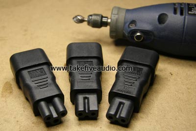
This simple recipe uses an adapter as the plug. The adapter can be
modified so that the contacts are accessed easily in order to make a
solder connection. The adapter you choose to make this cord will be
determined by the requirements of the component you wish to use it on.
This recipe can use the C7 or C7 Polarized adapter. For this recipe we used the Belden 19364as the cable, I still use the cable pictured here on my DVD player, it performs quite
well in this application. The purpose of this recipe is not so much to
suggest a cable to use, as it is to show how the adapters can be
directly attached to a cord.


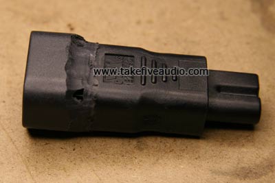
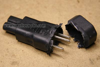
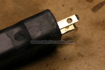
The first step is to modify the adapter. We used a
dremel type tool with a rotary file to carefully remove the portion of
the adapter that shrouds the contact pins. You can cleanly remove the
shroud by grinding off the shoulder and snapping the plastic shroud
off. When the shroud is removed then you can clean up the area and
round the edges.
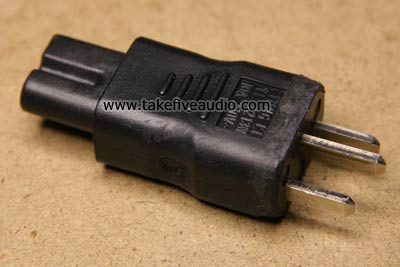
The next step will be to remove the ground pin from
the adapter, on the C7 adapter the ground pin is not connected to
either of the female terminals. A strong pair of side cutters will
remove the prong.
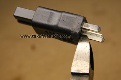
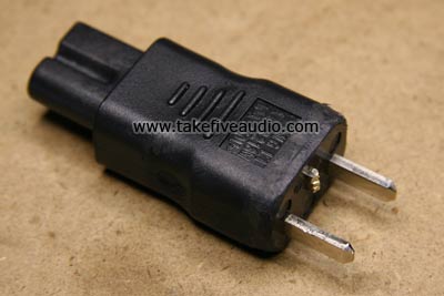
Next, drill two small holes in the remaining
two terminals, this will enable you to make a good mechanical
connection to the conductors before soldering.
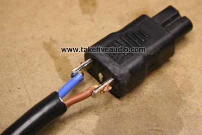
Strip about 1.5" of the jacket from the end of the
19364 and remove the foil shield, snip the ground wire and drain wire
back flush with the jacket. Next strip .5" of the insulation from the
remaining two conductors and put them through the holes with the
insulation to the inside of the prongs. Now solder the conductors to
the prongs. At this point you should make careful notes as to the
polarity of the 2 wires. If you look closely at the adapter you will
see the letters "N", "L" and "E" molded into the plastic under the
prongs. These letters mark the polarity and ground. "N" = Neutral or -,
"L" = Live or +. "E" = Earth or ground. make certain you maintain the
same polarity on the wall plug end.
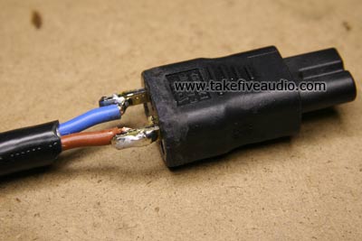
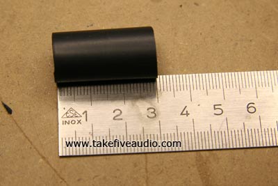
Next we cover the solder connection with a 30 mm
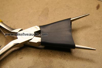
piece of CPA 100 1/2" shrinktube. You will need to stretch the tubing
with your pliers as shown here to get it all the way over the contacts.
It is not shown in these pictures but the bare contacts and the solder
connections were covered with several layers of Teflon plumbers tape
before applying the shrinktube.
